Flow diagram of different modules for the designed autonomous car Circuit Diagram
Flow diagram of different modules for the designed autonomous car Circuit Diagram Fig. 2: Block diagram of the obstacle-avoiding robot Fig. 3: Circuit diagram of the obstacle-avoiding robot. The ultrasonic sensor is vital for this project. It transmits ultrasonic signal bursts at 40 kHz, which bounce back when an object is detected. In conclusion, the Obstacle-Avoiding Autonomous Car Robot exhibits robots' amazing

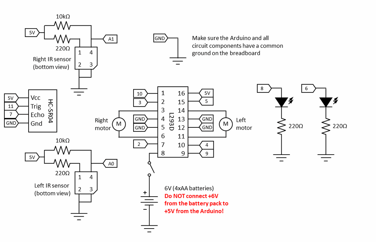
wiring diagram exactly, the code will not work properly. Take your time and carefully double-check all of your wiring. This is a complicated circuit with a lot of connections. You should connect the autonomous-car-circuit-diagram.png) Figure 5. Male-female jumper wires connected to the IR sensor's pins.
Science Fair Project Ideas, Answers, & Tools Circuit Diagram
In this project we will learn how to build a self driving car that avoid any obstacles. Components needed Arduino Uno Jumper Cables 9 volt battery L298N Motor Driver 2 DC Motors 2 wheels 1 caster wheel Ultrasonic Sensor What is an L298N Motor Driver? One thing i noticed is the image of the Arduino used in the 'Completed Circuit' diagram Download scientific diagram | Autonomous vehicle system block diagram [1]. from publication: Improving the Learning of Self-driving Vehicles Based on Real Driving Behavior using Deep Neural

provided by the circuit which is programmed in computer using C++ language and its Libraries. Since C++ is a very fast programming language a well compatible by the arduino board the robot doesn't needs much time to follow these commands. Fig. 2: Circuit Diagram for autonomous car 3.1. Arduino Uno * * The code will read the sensors and is set up to control the speed and direction of the robot's two motors * using an H-bridge integrated circuit (the L293D, included in your Bluebot kit). However, *you* must write * an algorithm that determines what the robot will do based on the sensor readings.
PDF Autonomous Car Using Raspberry Pi Circuit Diagram
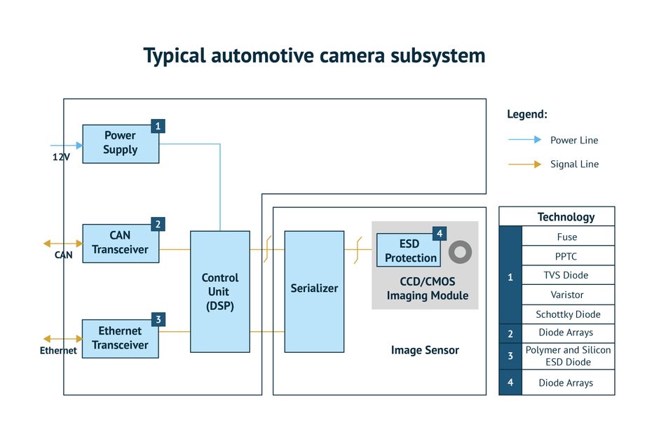
Fig -8: Block diagram of self-driving car This model aims at designing an autonomous car prototype using Raspberry Pi as a processing chip. An HD camera along with an ultrasonic sensor is used to provide necessary data from the real world to the car. The car is capable of moving on its own thus avoiding the risk of human errors.