Download Scientific Diagram Circuit Diagram
Download Scientific Diagram Circuit Diagram The circuit diagram : Infrared sensor circuit is very simple and straight forward. Circuit is divided into two sections. IR TX and IR RX are to be soldered on small general purpose Grid PCB. From this module, take out 3 wires of sufficiently long length (say 1 ft). Then, as shown above, connect them to VCC, preset and to ground on main board.

How to make proximity sensor. Simple IR Proximity Sensor Circuit. Diy IR Sensor ..Welcome to our channel "PendTech"I'm .Puspendu Ghosh🔘 ABOUT THIS VIDEO
Intro to IR Circuits : 9 Steps (with Pictures) Circuit Diagram
The first step of our build is to assemble the components for the circuit. The main components for our IR sensor circuit are the IR sensor itself, a few resistors, a capacitor, an LED, and an Arduino board. These items can usually be found at any electronics shop, online or locally. Once we have our components, we need to connect them to the

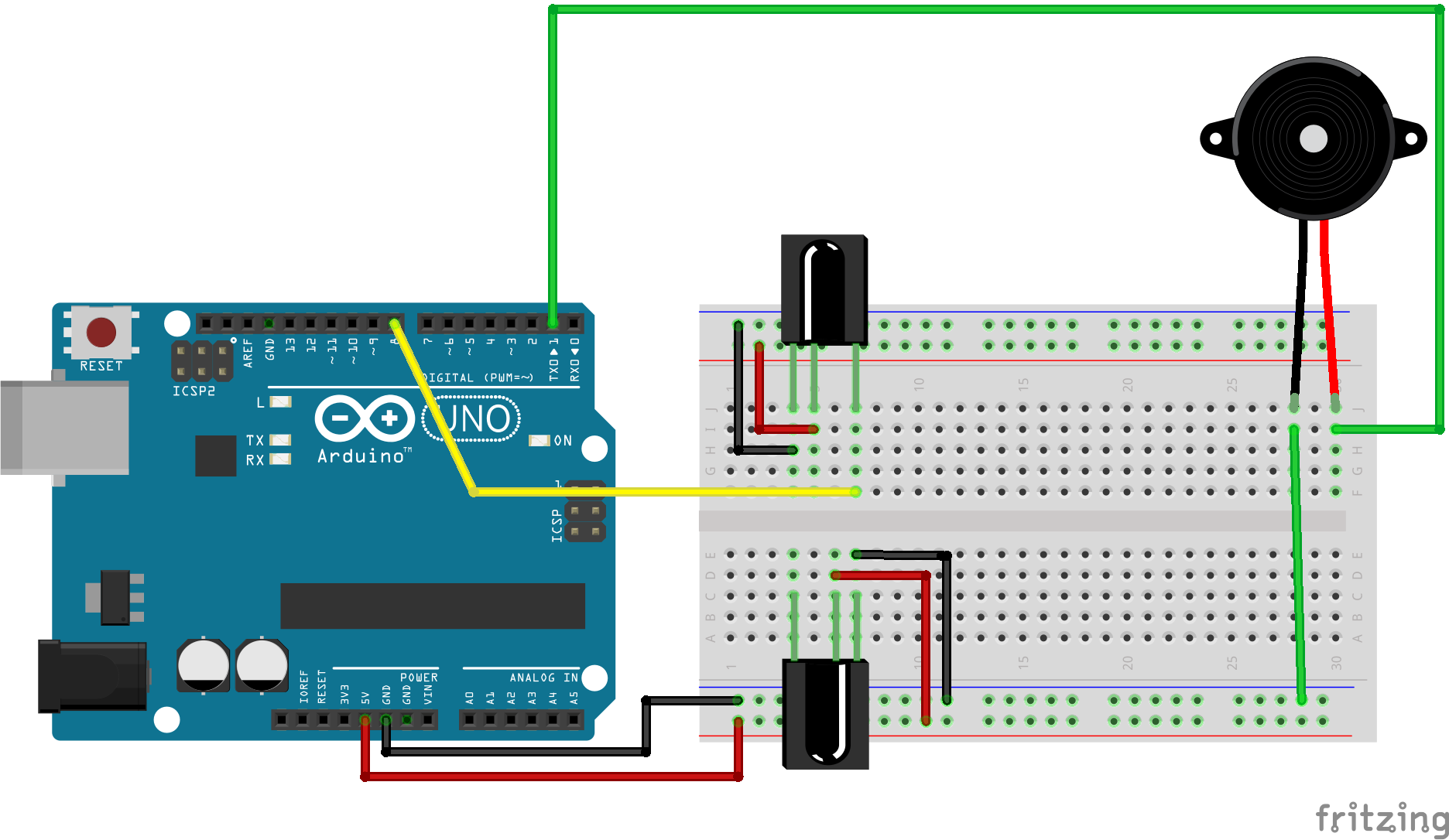
This project demonstrates how to create a basic circuit using an IR sensor, buzzer, and LiPo battery, with no Arduino involved. The IR sensor triggers the bu

Simple IR Proximity Sensor With Arduino Circuit Diagram
DIY - IR Module: A sensor is a device that detects and responds to inputs from the physical environment. The input can be light, heat, motion, moisture, pressure, or any other environmental phenomena. an IR Module is a combination of a IR transmitter and receiver circuit. Infrared light emitted by the IR LED is detected by the Photodiode

// Simple Proximity Sensor using Infrared // Description: Measure the distance to an obstacle using infrared light emitted by IR LED and // read the value with a IR photodiode. The accuracy is not perfect, but works great // with minor projects. // Author: Ricardo Ouvina // Date: 01/10/2012 // Version: 1.0